Bacopa: 6-Channel LED Driver / Carrier for Buce
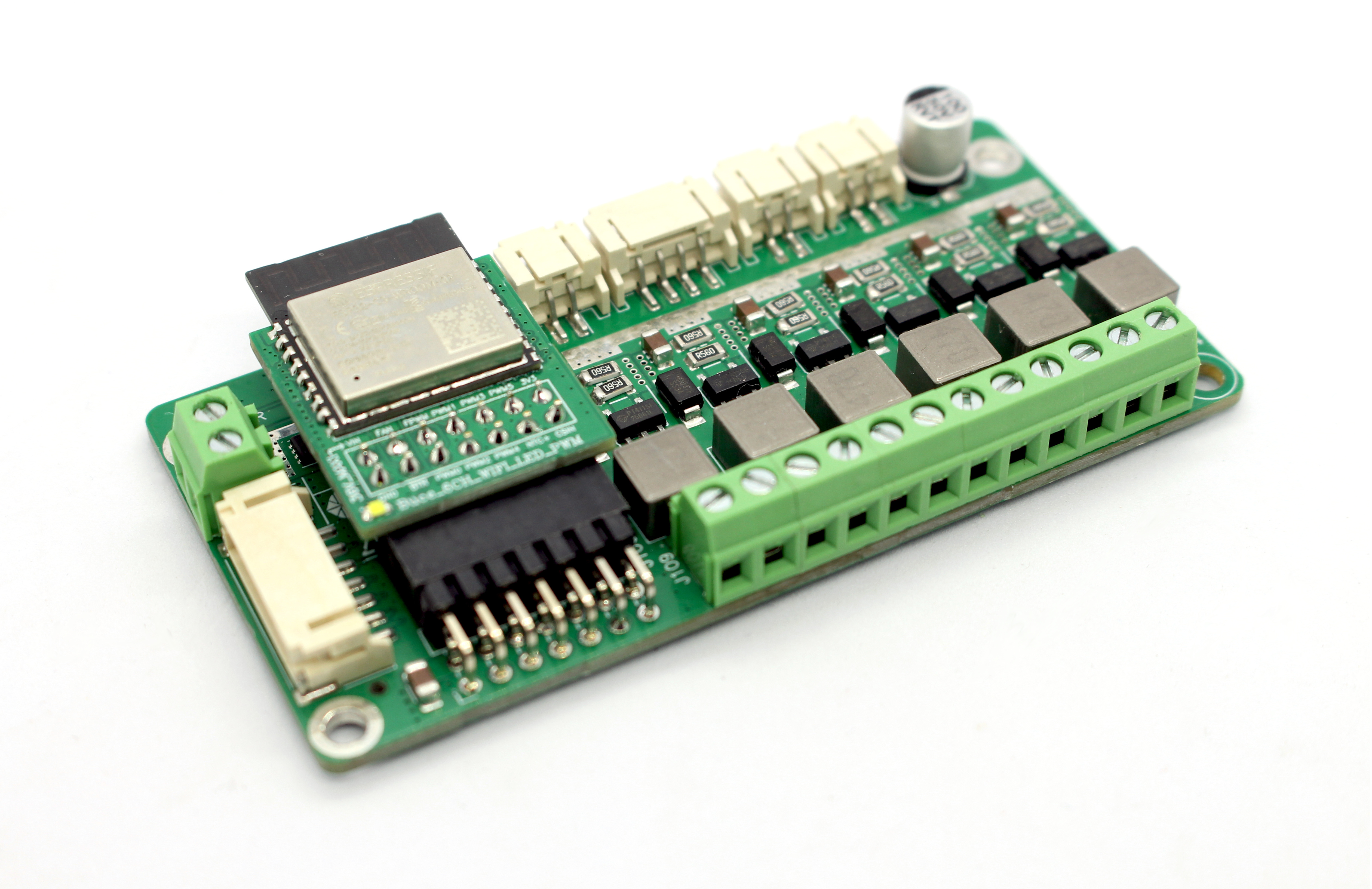
The Appearance of Bacopa Module
Overview
Bacopa is the LED driver/carrier board for the Buce 6-channel WiFi LED controller (BLC06). Engineered with premium components and careful design, Bacopa delivers 700 mA constant-current output per channel, capable of driving a total of up to 162 W of LEDs (approximately 54 × 3 W high-power LED beads).
Under the control of the Buce LED controller’s 6-channel phase-shifted interleaved output, 12-bit duty cycle resolution, and up to 19.5 kHz ultra-high-frequency PWM dimming signal, completely flicker-free smooth dimming is achieved while fully eliminating audible noise from inductors and ceramic capacitors.
BLM06 integrates reverse-polarity protection circuitry and a current sensor. In conjunction with the Buce controller, it provides not only up to 130 W constant-current power output but also reverse-polarity, over-temperature, and over-current protection. Combined with the companion controller’s multi-segment programmable dimming, astronomical algorithm-based sunrise/sunset simulation, moonlight simulation, adaptive thermal management, and LED power monitoring, it serves as the ideal core hardware for premium aquarium luminaires, indoor agriculture/horticultural lighting, and smart lighting applications.
Features
Wide input voltage range: 6 to 36 V
Constant-current output voltage range: 2 to 32 V
6-channel independent 700 mA LED constant-current output
Maximum continuous output power of 130 W (equivalent to 162 W industry rating)
Efficiency up to 97%
Reverse-polarity, over-temperature, and over-power protection
4-layer PCB with shielded integrated inductors for EMI suppression
On-board TI INA139 high-side current sensor
Compact credit-card form factor: 85 × 42 mm
Easy-to-install 2.0 mm board-to-board/ribbon connectors and screw terminals
DIN35 rail mount via accessory bracket
Please checkout the following datasheets for more information about the hardware.
Usage
Pinout

Pinout Diagram
Port# |
Name |
Type |
Description |
|---|---|---|---|
① |
Power |
3.81 mm Screw Terminal |
6–36 V power supply positive and negative inputs; terminal rated for up to 10 A |
② |
PWM Signal Output |
2.0 mm Board-to-Board Connector |
Optional parallel PWM signal output for daisy-chaining multiple driver modules |
③ |
Constant-Current Power Output |
3.81 mm Screw Terminal |
Constant-current output for driving LED strings; connect one independent LED string circuit per group |
④ |
2-Wire Fan Drive Output |
2.0 mm Board-to-Board Connector |
12 V two-wire fan speed-control drive output; direct fan connection supported |
⑤ |
PWM Fan Output |
2.0 mm Board-to-Board Connector |
12 V four-wire fan power output; direct PWM fan connection supported |
⑥ |
NTC Input |
2.0 mm Board-to-Board Connector |
Connection for 10 kΩ, B3950 NTC thermistor |
⑦ |
Button Input |
2.0 mm Board-to-Board Connector |
Optional button for temporary lighting toggle and long-press network reconfiguration |
Typical Peripheral Circuit
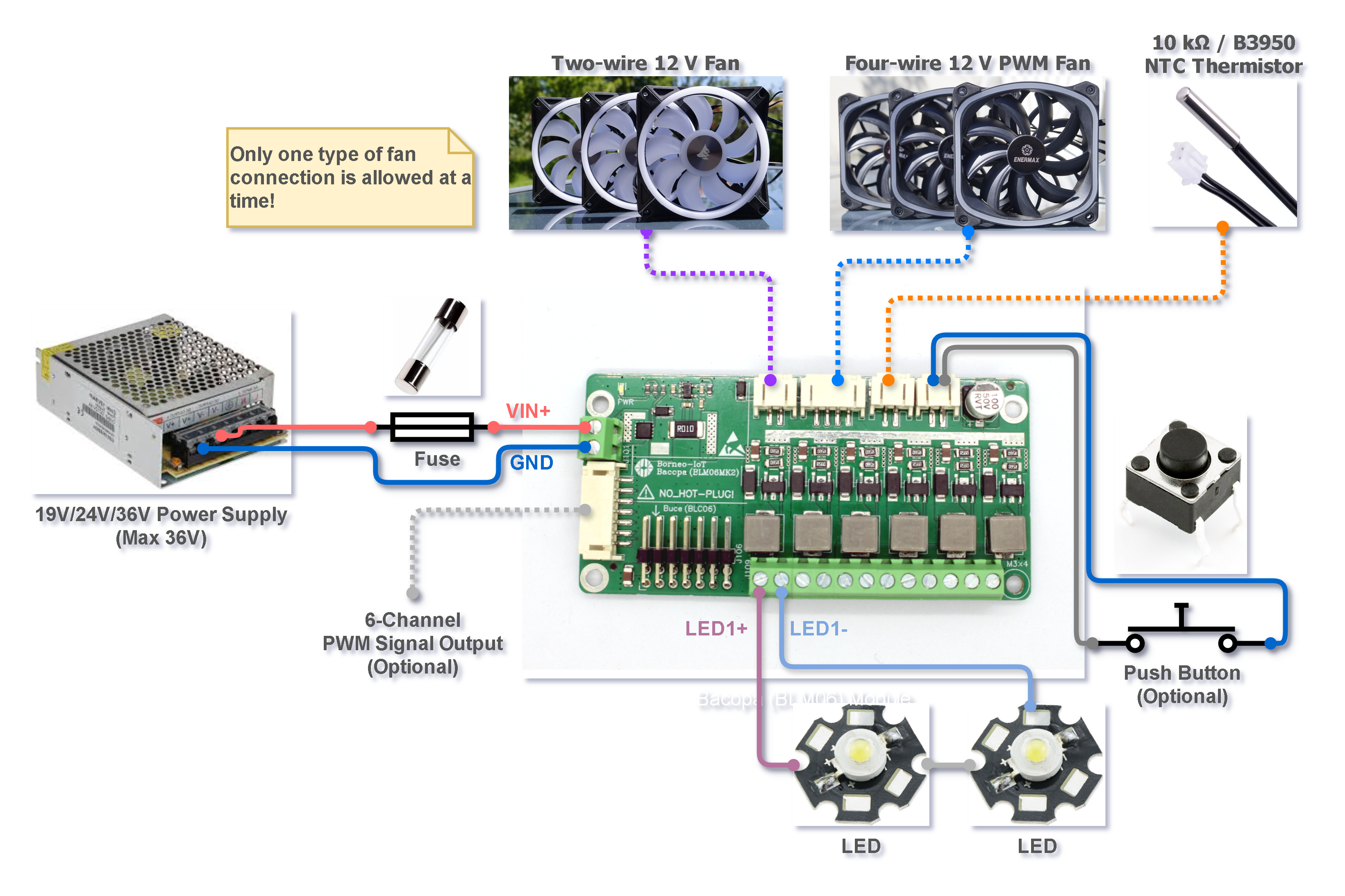
Typical Circuit Diagram